January 2011 Edition
Computer Science Department, University of Cape Town
| MIT Notes Home | Edition Home |
| MSc-IT Study Material January 2011 Edition Computer Science Department, University of Cape Town | MIT Notes Home | Edition Home | |
We have already seen how a level 0 context diagram can be decomposed (exploded) into a level 1 DFD. In DFD modeling terms we talk of the context diagram as the “parent” and the level 1 diagram as the “child”.
This same process can be applied to each process appearing within a level 1 DFD. A DFD that represents a decomposed level 1 DFD process is called a level 2 DFD. There can be a level 2 DFD for each process that appears in the level 1 DFD.
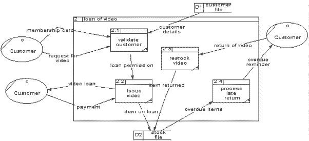
A possible level 2 DFD for process “2: Loan of video” of the level 1 DFD is as follows:
Note, that every data-flow into and out of the parent process must appear as part of the child DFD. The numbering of processes in the child DFD is derived from the number of the parent process – so all processes in the child DFD of process 2, will be called 2.X (where X is the arbitrary number of the process on the level 2 DFD). Also there are no new data-flows into or out of this diagram – this kind of data-flow validation is called balancing.
Look at the rectangular boundary for this level 2 DFD. Outside the boundary is the external entity “Customer”. Also outside the boundary are the two data stores – although these data stores are inside the system (see the level 1 DFD), they are outside the scope of this level 2 DFD.
The level 1 data-flow diagram provides an overview of the system. As the software engineers' understanding of the system increases it becomes necessary to expand most of the level 1 processes to a second or even third level in order to depict the detail within it. Decomposition is applied to each process on the level 1 diagram for which there is enough detail hidden within the process. Each process on the level 2 diagrams also needs to be checked for possible decomposition, and so on.
A process box that cannot be decomposed further is marked with an asterisk in the bottom right hand corner. A brief narrative description of each bottom-level process should be provided with the data-flow diagrams to complete the documentation of the data-flow model. These make up part of the process definitions which should be supplied with the DFD.
Each process on the level 1 diagram is investigated in more detail, to give a greater understanding of the activities and data-flows. Normally processes are decomposed where:
There are more than six data-flows around the process
The process name is complex or very general which indicates that it incorporates a number of activities.
The following steps are suggested to aid the decomposition of a process from one DFD to a lower level DFD. As you can see they are very similar to the steps for creating a level 1 DFD from a context diagram:
Make the process box on the level 1 diagram the system boundary on the level 2 diagram that decomposes it. This level 2 diagram must balance with its “parent” process box — the data-flows to and from the process on the level 1 diagram will all become data-flows across the system boundary on the level 2 diagram. The sources and recipients of data-flows across the level 2 system boundary are drawn outside the boundary and labelled exactly as they are on the level 1 diagram. Note that these sources and recipients may be data stores as well external entities or other processes — this is because a data store in a level 1 diagram will be outside the boundary of a level 2 process that sends or receives data-flows to/from the data store.
Identify the processes inside the level 2 system boundary and draw these processes and their data-flows. Remember, each data-flow into and out of the level 2 system boundary should be to/from a process. Using the results of the more detailed investigation, filter out and draw the processes at the lower level that send and receive information both across and within the level 2 system boundary. Use the level numbering system to number sub-processes so that, for example, process 4 on the level 1 diagram is decomposed to sub-processes 4.1, 4.2, 4.3 … on the level 2 diagram.
Identify any data stores that exist entirely within the level 2 boundary, and draw these data stores.
Identify data-flows between the processes and data stores that are entirely within the level 2 system boundary. Remember, every data store inside this boundary should have at least one input and one output date flow.
Check the diagram. Ensure that the level 2 data-flow diagram does not violate the rules for data-flow diagram constructs.