Figure 7.1
Table of contents
At the end of this chapter you should be able to:
Describe the concepts of specialization/generalization, aggregation and composition.
Illustrate how specialization/generalization, aggregation and composition are represented in ER diagrams.
Map the specialization/generalization relationship to tables suitable for Relational database implementation.
In parallel with this chapter, you should read Chapter 12 of Thomas Connolly and Carolyn Begg, "Database Systems A Practical Approach to Design, Implementation, and Management", (5th edn.).
This chapter builds on the previous chapter which addressed the basic concepts of Entity-Relationship (ER) modelling. The chapter discussed the concepts of an entity, participation, recursive relationships, weak entities and strong entities. It also illustrated how these concepts can be represented in the ER diagrams. Improved computer speed and memory has, in recent years, triggered the development of sophisticated software applications like Geographical Information Systems (GIS). The basic features of ER modelling are not sufficient to represent all the concepts in such applications. To address these needs, many different semantic data models have been proposed and some of the most important semantic concepts have been successfully incorporated into the original ER model. This chapter discusses and illustrates advanced ER modelling concepts, namely specialization/generalization, aggregation and composition.
This chapter continues to address the top-down database design concepts. Like the previous chapters, it links closely with the other chapters on database design, Normalisation and other design topics. The chapter also has considerable relevance for the material in the module on performance tuning, such as the chapter on indexing, as the decisions made during database design have a major impact on the performance of the application.
In the previous chapter, we discussed basic concepts of ER modelling. This sections revisits some of the important concepts covered.
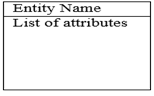
An entity may represent a category of people, things, events, locations or concepts within the area under consideration. An entity can have one or more attributes or characteristics. Two notations for representing an entity are common: box notation, and the notation that employs ellipses to represent the attributes belonging to an entity.
Figure 7.1
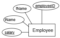
Figure 7.2
These express the number of entities with which another entity can be associated via a relationship. The relationships that exist between two entities can be categorised by the following:
• one-to-one
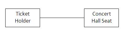
Figure 7.3
• one-to-many
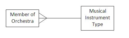
Figure 7.4
• many-to-many
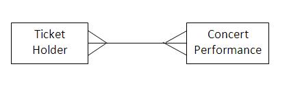
Figure 7.5
The participation condition defines whether it is mandatory or optional for an entity to participate in a relationship. This is also known as the membership class of a relationship.
There are two kinds of participation conditions: mandatory and optional. Most entities are involved in binary relationships, so it follows that there are four main types of membership relationships:
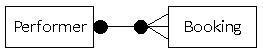
Figure 7.6
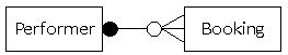
Figure 7.7
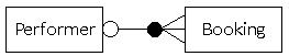
Figure 7.8
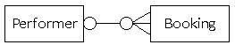
Figure 7.9
Note: We have used the one-to-many relationship type to illustrate participation. Refer to the previous chapter for more details on how to model participation for other relationship types.
We have discussed different types of relationships that can occur between entities. Some entities have relationships that form a hierarchy. For example, a shipping company can have different types of ships for its business. The relationship that exists between the concept of the ship and the specific types of ships forms a hierarchy. The ship is called a superclass. The specific types of ships are called subclasses.
Superclass: An entity type that represents a general concept at a high level.
Subclass: An entity type that represents a specific concept at lower levels.
A subclass is said to inherit from a superclass. A subclass can inherit from many superclasses in the hierarchy. When a subclass inherits from one or more superclasses, it inherits all their attributes. In addition to the inherited attributes, a subclass can also define its own specific attributes. A subclass also inherits participation in the relationship sets in which its superclass (higher-level entity) participates.
The process of making a superclass from a group of subclasses is called generalization. The process of making subclasses from a general concept is called specialization.
Specialization: A means of identifying sub-groups within an entity set which have attributes that are not shared by all the entities (top-down).
Generalization: Multiple entity sets are synthesized into a higher-level entity set, based on common features (bottom-up).
A diamond notation is a common representation of specialization/generalization relationships in ER diagrams.
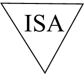
Figure 7.10
As an example, let’s consider the following scenario:
Africa holds many historical artefacts in different locations. Each artefact is kept in a specific location. A location can be a point, province, country or sub-region of Africa.
The scenario has a specialization relationship between the location and different specific types of locations (i.e. point, province, country and sub-region). This specialization relationship is represented in the ER diagram below.
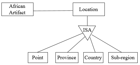
Figure 7.11
To demonstrate generalization, let’s imagine that an Artefact is one of the examples of the African cultural items. Another type of a cultural item is an Artist. It is clear to see that a cultural item is a superclass of an artefact and artist. This generalization relationship can be represented in the ER diagram as show below.
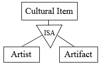
Figure 7.12
There are three constraints that may apply to a specialization/generalization: membership constraints, disjoint constraints and completeness constraints.
Membership constraints
Condition defined: Membership of a specialization/generalization relationship can be defined as a condition in the requirements e.g. tanker is a ship where cargo = “oil”
User defined: Sometimes the designer can define the superclass-subclass relationship. This can be done to simplify the design model or represent a complex relationship that exists between entities.
Disjoint constraints
Disjoint: The disjoint constraint only applies when a superclass has more than one subclass. If the subclasses are disjoint, then an entity occurrence can be a member of only one of the subclasses, e.g. postgrads or undergrads – you cannot be both. To represent a disjoint superclass/subclass relationship, ‘Or’ is used.
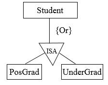
Figure 7.13
Overlapping: This applies when an entity occurrence may be a member of more than one subclass, e.g. student and staff – some people are both. ‘And’ is used to represent the overlapping specialization/generalization relationship in the ER diagram.
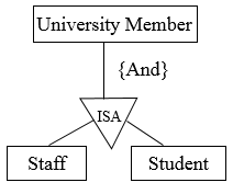
Figure 7.14
Completeness constraints
Total: Each superclass (higher-level entity) must belong to subclasses (lower-level entity sets), e.g. a student must be postgrad or undergrad. To represent completeness in the specialization/generalization relationship, the keyword ‘Mandatory’ is used.
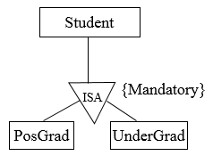
Figure 7.15
Partial: Some superclasses may not belong to subclasses (lower-level entity sets), e.g. some people at UCT are neither student nor staff. The keyword ‘Optional’ is used to represent a partial specialization/generalization relationship.
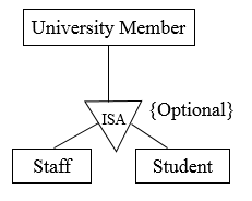
Figure 7.16
We can show both disjoint and completeness constraints in the ER diagram. Following our examples, we can combine disjoint and completeness constraints.
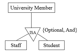
Figure 7.17
Some members of a university are both students and staff. Not all members of the university are staff and students.
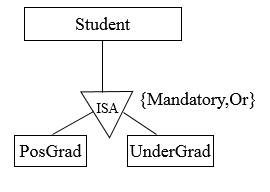
Figure 7.18
A student in the university must be either an undergraduate or postgraduate, but not both.
Specialization/generalization relationship can be mapped to relational tables in three methods. To demonstrate the methods, we will take the student, postgraduate and undergraduate relationship. A student in the university has a registration number and a name. Only postgraduate students have supervisors. Undergraduates accumulates points through their coursework.
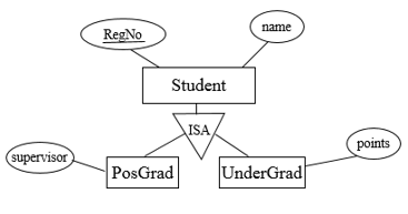
Figure 7.19
Method 1
All the entities in the relationship are mapped to individual tables.
Student (Regno, name)
PosGrad (Regno, supervisor)
UnderGrad (Regno, points)
Method 2
Only subclasses are mapped to tables. The attributes in the superclass are duplicated in all subclasses.
PosGrad (Regno, name, supervisor)
UnderGrad (Regno, name, points)
This method is most preferred when inheritance is disjoint and complete, e.g. every student is either PosGrad or UnderGrad and nobody is both.
Method 3
Only the superclass is mapped to a table. The attributes in the subclasses are taken to the superclass.
Student (Regno, name, supervisor, points)
This method will introduce null values. When we insert an undergraduate record in the table, the supervisor column value will be null. In the same way, when we insert a postgraduate record in the table, the points value will be null.
Review question 1
Discuss the specialization/generalization relationship in ER modelling.
Review question 2
Explain the three constraints that can be applied on the specialization/generalization relationship.
Aggregation represents a ‘has-a’ relationship between entity types, where one represents the ‘whole’ and the other the ‘part’.
An example of aggregation is the Car and Engine entities. A car is made up of an engine. The car is the whole and the engine is the part. Aggregation does not represent strong ownership. This means, a part can exist on its own without the whole. There is no stronger ownership between a car and the engine. An engine of a car can be moved to another car.
A line with a diamond at the end is used to represent aggregation.

Figure 7.20
The ‘whole’ part must be put at the end of the diamond. For example, the Car-Engine relationship would be represented as shown below:
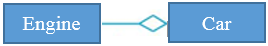
Figure 7.21
Composition is a form of aggregation that represents an association between entities, where there is a strong ownership between the ‘whole’ and the ‘part’. For example, a tree and a branch have a composition relationship. A branch is 'part' of a 'whole' tree - we cannot cut the branch and add it to another tree.
A line with a filled diamond at the end is used to represent composition.

Figure 7.22
The example of the Tree-Branch relationship can be represented as shown below:
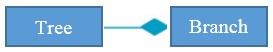
Figure 7.23
Review question 3
Using an example, explain the concepts of aggregation and composition.
Exercise 1
Draw the ER diagram for a small database for a bookstore. The database will store information about books for sale. Each book has an ISBN, title, price and short description. Each book is published by a publisher in a certain publishing year. For each publisher, the database maintains the name, address and phone number.
Each book is written by one or more authors. For each author, the database maintains his/her ID, name and a short introduction. Each book is stored in exactly one warehouse with a particular quantity. For each warehouse, the database maintains the warehouse name, the location and the phone number. Each book has one or more sellers, which may be either companies (corporate vendors) or individuals (individual vendors).
For each company, the database maintains a name of the company, its address, its phone numbers (there could be more than one phone number, each with a number and a description) and its contact person. For each individual vendor, the database keeps a name, a phone number and an email address. A contact person whose company sells a book cannot be selling the same book as an individual vendor at the same time (he/she may sell other books as an individual seller).
In previous chapters, we introduced database technology and how it is used by businesses to store data in a structured format. XML (eXtensible Markup Language) has become a standard for structured data interchange among businesses. It was formally ratified by the World Wide Web Consortium (W3C) in 1998. XML uses markup for formatting plain text. Markup refers to auxiliary information (tags) in the text that give structure and meaning.
We have demonstrated how to use relational tables to represent entities and their attributes. XML also supports the representation of entities and attributes.
In this section, we will introduce XML. Students are encouraged to study detailed books for further information. One useful website for learning XML is http://www.w3schools.com/xml/default.asp.
An element is a building block of an XML document.
All elements are delimited by < and >.
Element names are case-sensitive and cannot contain spaces.
The representation of an element is shown below:
<Element> …. </Element>
An XML document can contain many elements, but one must be the root element. A root element is a parent element of all other elements.
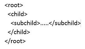
Figure 7.24
Elements can have attributes. Attributes are specified by name=value pairs inside the starting tag of an element:
<Element attribute = “value” >.. </Element >
All values of the attributes are enclosed in double quotes.
An element can have several attributes, but each attribute name can only occur once.
<Element attribute1 = “value1” attribute2=“value2”>
To demonstrate XML, let’s imagine we have a customer table that holds information of customers.
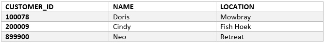
Figure 7.25
We can represent the information in XML as follows:
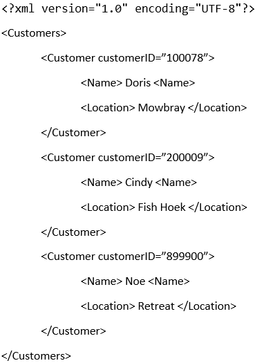
Figure 7.26
Explanation
<?xml version="1.0" encoding="UTF-8"?>: is the XML prolog. The prolog is used to specify the version of XML and the encoding used. It is optional, but if it appears in the document, it must be the first line in the document.
Customers element: Customers is the root element.
Customer element: A Customer element represents a tuple in the Customers table. The table has three attributes, CUSTOMER_ID, NAME and LOCATION. In our XML, CUSTOMER_ID is represented as an attribute of the Customer element. NAME and LOCATION are represented as child elements of the Customer element. Notice that we have repeated the Customer element three times to capture the three records in the Customer table.
The XML technology specifies the syntax for writing well-formed documents but does not impose the structure of the document. XML document writers are free to structure an XML document in any way they want. This can be problematic when verifying a document. How many elements can a document have? What elements should a document have? These questions are difficult to answer unless we also specify the structure of the document. Document type definition (DTD) is used to define the structure of an XML document.
DTD specifies the following:
What elements can occur.
What attributes an element can/must have.
What sub-elements can/must occur inside each element, and how many times.
DTD element syntax:
<!ELEMENT element (subelements-specification) >
DTD attribute syntax:
<!ATTLIST element (attributes) >
The DTD for the XML we defined above can be defined as shown below:
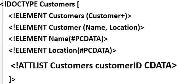
Figure 7.27
Explanation
!DOCTYPE: Defines that the Customers element is the root element of the document.
<IELEMENT>: Defines an XML element. The first element to be defined is the Customers element. A Customers element has one child element, Customer, indicated in brackets. The + symbol means that the Customer element can appear one or more times under the Customers element. The Customer has two sub-elements, Name and Location. The Name and Location elements have character data as a child element.
<!ATTLIST>: Defines the attribute. The Customers element has one attribute, customerID, of type character data.
XML data has to be exchanged between organisations. The same element name may have different meaning in different organisations, causing confusion on exchanged documents.
Specifying a unique string as an element name avoids confusion. A better solution is to use a unique name followed by an element name.
unique-name:element-name
Adding a unique name to all element names can be cumbersome for long documents. To avoid using long unique names all over a document, we can use XML namespaces.
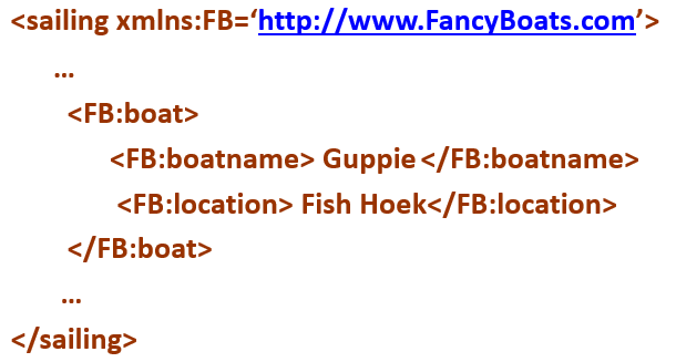
Figure 7.28
The namespace FB has been declared and initialised to ‘http://www.FancyBoats.com’. Namespaces are URIs. URIs are generic identifiers like URLs.
XQuery is a language for finding and extracting elements and attributes from XML documents. The way SQL is to relational databases, XQuery is the query language for XML documents. For example, to display all the names of the customers in the XML above, our XQuery will look as follows:
for $x in /Customers/Customer
return $x/Name
Exercise 2
In chapter 3, Introduction to SQL, we introduced the EMP table. Represent the records in the table in XML.