Figure 3.1: TCP/IP layers mapped to OSI Reference model layers
Table of contents
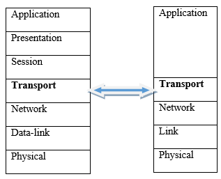
The transport layer provides logical communication between application layer processes running on different hosts so that it appears as if these processes are directly connected. In terms of OSI layers, the transport layer lies between the Network and Session layers. However, in terms of TCP/IP, the transport layer lies between the application layer and the network layers, as shown in 3.1. In this chapter, we will discuss Transport layer protocols in TCP/IP protocol suite.
Figure 3.1: TCP/IP layers mapped to OSI Reference model layers
In the previous two chapter we gave a brief overview of the TCP/IP transport layer protocols, namely, User Datagram Protocol (UDP) and Transmission Control Protocol (TCP). This chapter continues the discussion of UDP and TCP but in more details.
UDP is a connectionless protocol in the sense that a connection will not be established between application processes before exchanging data. UDP does not guarantee that messages will reach the receiving application. Furthermore, messages may arrive out of order. This particular feature makes UDP provide speedy delivery of messages between applications, at the expense of reliability.
TCP on the other hand grantees reliability. Application processes make a connection before application messages can be exchanged. A reliable transfer of data means that to the application layer, it appears as if no data bits were corrupted (flipped from 0 to 1, or vice versa) or lost en route, and all bits are delivered in the order in which they were sent. While data corruption or loss may have occurred along an unreliable channel, the transport layer (in this case) employs mechanisms to fix these errors and ensure that packets are delivered in order.
By the end of this Chapter you should be able to:
Know the main data unit of the transport layer
Understand the processes of multiplexing and de-multiplexing in the Transport layer
Understand how transport layer ports relate to process sockets
Note the services provided and functions performed by UDP
Note the services provided by TCP
Understand mechanisms TCP uses to ensure reliability
Know the abstraction of the network the transport layer presents to the higher layers
Discuss at a high level the connection establishment process of TCP and how specific fields in the segment header are integral to this process
Understand the principles of congestion control in the context of the transport layer
Explain the main states involved in the TCP congestion control process
Give some examples of congestion avoidance algorithms used by different operating systems
Note the distinguishing features between TCP and UDP
Before we delve in the details of UDP and TCP, let’s quickly review some of the concepts we have already learned in previous chapters.
Port Numbers
A port number is a 16-bit number, ranging from 0 to 65536, assigned to an application process for identification on the Internet. Some port numbers are reserved for popular Internet application. For example, port 80 is reserved for the Web Server. Whenever a new Internet application is developed, a port number must be assigned to it.
Transport layer segment
The transport layer converts the application layer messages it receives from a sending application process into transport layer packets, known as transport layer segments. In this conversion, application messages may need to be broken into smaller chunks. The transport layer attaches a header to each chunk, which typically contains information such as, the sending and receiving application ports.
Socket
A socket is a software interface between the transport layer and the application layer. The transport layer offers a set of services to the application layer. The socket provides the abstraction to access these services.
A host on the internet can have many Internet applications installed on it. All these applications will depend on the transport layer to deliver messages to other hosts. The transport layer at the sender side will receive messages from different applications, break the message into segments and pass them on to the underlying network layer. This job of the transport layer is known as Multiplexing (illustrated on the left side of Figure 3.2). De-multiplexing occurs at the receiver’s side. The transport layer gathers the segments from the network layer, retrieve the port number from the segments and passes the segments to the appropriate application process (as shown in the right hand side of Figure 2).
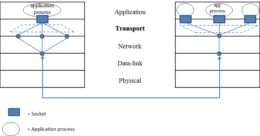
Figure 3.2: TRANSPORT LAYER MULTIPLEXING (LEFT) AND DE-MULTIPLEXING (RIGHT)
UDP is said to be connectionless because there is no connection setup between sending and receiving hosts at the transport layer before a segment is transmitted. UDP does not guarantee delivery of segments. Also, segments may arrive out of order at the receiving end. For this reason, UDP is said to be unreliable. While UDP is considered an unreliable protocol, it is possible for an application to have reliable data transfer when using UDP if reliability is built into the application itself. For instance, DNS uses UDP for client-server communication.
We have already mentioned that the transport layer may break messages received from the application layer into smaller chunks. UDP protocol attaches a UDP header to each chunk of data to make a UDP segment. In this section, we will look at the UDP header in details.
The UDP segment contains the header fields and a data field as shown in Figure 3.3. The data field contains a chunk of application data.
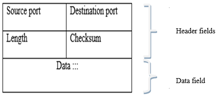
Figure 3.3: UDP SEGMENT STRUCTURE
Source port: holds the port number of the sending application. This is an optional field.
Destination port: holds the port number of the receiving application.
Length: the length field specifies the number of bytes in the full UDP segment, which is required since the size of the data field may differ from one UDP segment to the next.
Checksum: The checksum field is used for end-to-end error checking. This is done through applying a checksum, which can determine whether bits within the UDP segment have been altered along the path from source to destination. This error checking cannot, however, fix the problem. The result is either to discard the damaged segment or pass it on to the application with a warning.
Data: contains a chunk of application data.
To illustrate how UDP works, let’s assume application A wants to send a message to B.
UDP will do the following at A:
A’s port number
B’s port number
length of the chunk + length of the UDP header
checksum
At B, UDP will do the following:
gathers segments from the network layer
perform a checksum for error checking
if the segments are okay, use the destination port number to deliver the received segments to B.
If you were developing an application in a host using Python, you could create a UDP socket with the line
clientSocket = socket(socket.AF_INET, socket.SOCK_DGRAM)
You could then bind a specific port number in the range 1024 to 65536 (in this case 19157) to the socket with the line
clientSocket.bind((‘’, 19157))
or if writing server-side software for a well-known protocol you would have to use the appropriate port number. If this line is not added, the transport layer automatically assigns a port number in that range and, if that is not already in use, to the socket. Typically, the client side of an application lets the transport layer automatically (and transparently) assign the port number, whereas the server side of an application assigns a specific port number.
Unlike UDP, TCP is connection-oriented. Application processes must first make a connection before messages can be exchanged. TCP protocol provides more services to the application layer than its counterpart – UDP. Specifically, this includes error recovery, flow control, and reliability. Most of the application layer protocols we discussed in the previous chapter, such as HTTP, SMTP and FTP, use TCP.
Stream data transfer
Like UDP, TCP also breaks the application layer messages into segments. TCP protocol hides all these details from the application layer. From the application’s point of view, TCP transfer a continuous stream of bits through a network.
Reliability
TCP is implemented on top of a network layer. As we will see in the next chapter, TCP is specifically implemented on top a network layer protocol called Internet protocol (IP). When TCP receives messages from the application layer, it breaks them into segments and hands them over to the underlying Internet protocol (IP). The Internet protocol (IP) does not guarantee delivery of the segments. Therefore, it is the responsibility of the TCP protocol to ensure segments are delivered on the receiving side. To implement reliability, TCP assigns a sequence number to each segment transmitted, and expects an acknowledgment (ACK) from the receiving TCP layer. If the ACK is not received within a timeout interval, the data is retransmitted. Sequence number are used by the receiving TCP layer to arrange the segments in order.
Flow control: The receiving TCP, when sending an ACK back to the sender, also indicates to the sender the number of bytes it can receive without causing an overflow in its internal memory. The receiver may also need to buffer segments because the packets may arrive faster than it can deliver them to thee application.
Full duplex: TCP provides for concurrent data streams in both directions. If there is a TCP connection between Process A on one host and Process B on another host, then application layer data can flow from Process A to Process B at the same time as application layer data flows from Process B to Process A.
As mentioned earlier, TCP breaks the application layer messages into smaller chunks. TCP pairs each chunk of client data with a TCP header, thereby forming TCP segments. Figure 3.4 shows all the fields that make up a TCP segment.
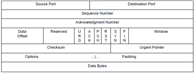
Figure 3.4: TCP SEGMENT STRUCTURE
Source Port: port number of the sending application process
Destination Port: port number of the receiving process.
Sequence Number: the sequence number of the first data byte in this segment. To understand how sequence numbers are assigned, suppose that the data stream consists of a file consisting of 10,000 bytes, that the maximum segment size is 1,000 bytes, and that the first byte of the data stream is numbered 0. TCP constructs 10 segments out of the data stream, each segment holding 1000 bytes. The first segment gets assigned sequence number 0, the second segment gets assigned sequence number 1,000, and the third segment gets assigned sequence number 2,000, and so on.
Acknowledgment Number: this field contains the value of the next sequence number that the receiver is expecting to receive.
Data Offset: indicates where the data begins in the segment.
Reserved: reserved for future use.
URG: indicates that the urgent pointer field is significant in this segment.
ACK: indicates that the acknowledgment field is significant in this segment.
PSH: indicates that the receiver should pass the data to the upper layer immediately.
RST: Resets the connection.
SYN: Synchronizes the sequence numbers.
FIN: No more data from sender to send.
Window: specifies the size of data bytes that the receiver is willing to accept.
Checksum: The checksum field is used for end-to-end error checking.
Urgent Pointer: Points to the location of the last byte of urgent data. Only significant when the URG control bit is set.
Options is used when a sender and receiver negotiate the maximum segment size or as a window scaling factor for use in high-speed networks.
Data Bytes: contains a chunk of application data.
A connection is established between a client and a server. TCP uses a three-way handshake mechanism to establish a connection. The client contacts the server to request a connection, the server responds with an acknowledgement (ACK) and then the client responds with its acknowledgement to let the server know the connection has successfully been opened. Specifically the three steps are:
Active open – the client sends a segment with its port number, the initial sequence number and set the SYN field in the header.
Passive open – the server sends a segment in response with its (the server’s) initial sequence number, its SYN field set and an acknowledgement of the initial sequence number of the server
Client acknowledgement. This segment may contain data payload while the above two segments carry no payload.
Acknowledgements have a set timeout so if a return acknowledgement segment is not received within that time the data is assumed to be lost and is retransmitted. This timeout value should be set to be longer than the connection’s (average) round trip time (RTT) but still reasonably short according to the application and the fluctuations in the RTTs over the network. Once an initial timeout has elapsed, the value of the timeout interval is doubled (in most implementations) and then doubled again after every retransmission until the maximum number of retransmissions is reached. When a new segment with a new sequence number is sent, the timeout interval is reset according to the most recent RTT estimates.
Congestion occurs in a network when the network resources, particularly its capacity, are overstrained with too much data to queue and transmit. This results in reduced quality of service, increased network delay and packet loss. Figure 3.5 illustrates a healthy network and network congestion. When the offered traffic load is far from the network capacity (maximum load it can carry) the throughput increases proportionately to the load. The desired condition is that offered traffic increases only to the point where it hovers just below network capacity so that all the offered traffic can be carried, but that network resources are not underused either. If the offered traffic approaches the network capacity and the routers or links are too slow, congestion starts to set in, packet loss may start to occur, which causes retransmissions, further straining the resources, and reducing the traffic the network is able to carry and the throughput. This has a self-perpetuating nature causing the network to spiral into further congestion and eventually network collapse. For this reason congestion control and avoidance, or mechanisms to remove congestion after it has happened and prevent it before it happens, are important to transport layer protocols.
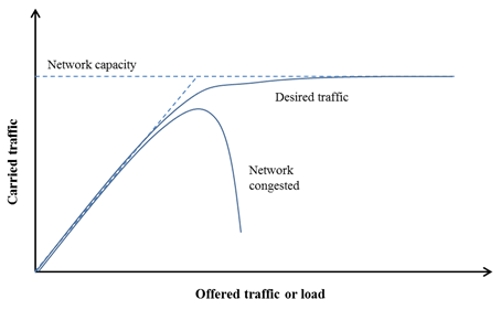
Figure 3.5: Network congestion
In TCP, senders limit the rate at which they send out data according to the perceived level of congestion – the higher the perceived congestion the slower the rate of sending data, whereas lower congestion enables faster rate of transmission. Enabling this process is the congestion window (cwnd), a value which is maintained independently at the sending side of every host in the network. The congestion window is maintained by the sender. Note that this is not to be confused with the TCP header window field discussed earlier. The TCP header window is set by the receiver telling the sender how many bytes it’s willing to receive.
The way congestion is detected by the sender is through dropped segments. When a datagram containing a TCP segment is dropped, this is picked up at the sender either by the timeout being reached before the transmission is acknowledged, or by the receipt of three duplicate ACKs. In general, TCP adjusts transmission rate by increasing the rate in response to positive ACKs that indicate a congestion-free network, until packet loss occurs, indicating the sending rate at which congestion starts. The transmission rate is slightly lowered again and then increased once more until packet loss occurs. In this way the connection is continually probed and transmission rates adjusted according to prevailing conditions.
A number of different TCP congestion control algorithms have been developed for different Operating systems. Examples of algorithms used by Linux include: CUBIC, Binary Increase Congestion control, Westwood and H-TCP. Windows operating system use Compound TCP. Explicit Congestion Notification (ECN) is used in MAC OS X, iOS and Solaris all use
When an application program tells TCP that it has no more data to send, TCP will close the connection in one direction by sending a segment with the FIN filed set in the header. Once a connection has been closed in a given direction, TCP refuses to accept more data for that connection. Meanwhile, data can continue to flow in the opposite direction until the sender closes it. When both directions have been closed, TCP at each endpoint deletes its record of the connection.
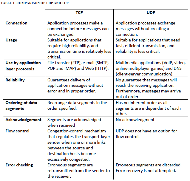
We conclude this chapter with the summary of the differences between UDP and TCP shown in Table 1 below.
What is the purpose of the Transport layer?
The transport layer aggregates (multiplexes) data from different applications into a single stream and passes it to which layer?
The endpoint of an inter-process communication flow across a computer network is called what?
What is happening between the instant at which a TCP transport connection is requested and the instant at which it is confirmed in a computer network?
Suppose a TCP connection has been established between two hosts, name A and B. If the TCP segments traveling from host A to B have a header with source port number as 37, and destination port number as 61, what would be the source and destination port numbers for the segments traveling from B to A?
What is another word for the universal port numbers used in the internet for specific services?
For the purposes of VoIP and IP video conferencing would you choose UDP or TCP as the transport layer protocol and justify the response?
When an application is run over UDP, which layer would take the overhead if reliability of data had to be ensured?
Why are TCP and UDP known as end-to-end protocols?
Describe (with the aid of a graph) the different phases of network load/overload outlining the degrees of congestion with increase of load. Indicate the point of congestion collapse and explain why it occurs. Where does TCP operate on that graph? Explain for the various phases of TCP; slow start, congestion avoidance (due to timeout), fast retransmit-fast recovery triggered by duplicate ACKs.
The Transport layer provides logical communication between application processes running on different hosts, performing transport layer multiplexing and de-multiplexing to ensure the data is delivered to the appropriate application process on the host computers, and passes down data to the network layer.
Network layer
Socket
Connection setup process
Source port = 61; destination port =37
Well-known port numbers
This is opinion based. An example response: UDP is preferable for these services. With TCP, delays happen every time there is packet loss or other errors because of retransmissions of undelivered packets and any following packets that may have already been seen. This results in an unacceptable level of jitter for the end user in real-time applications like VoIP. Real-time communications services such as VoIP do not require a completely reliable transport layer protocol. Errors like packet loss usually only have minor impacts on the audio output with UDP. It is perceptually better to have a few milliseconds of silence caused by a dropped packet than to have seconds of lag for retransmitting the dropped packet and all subsequent packets. However, it may be noted that since most firewalls are configured to block UDP traffic, using TCP for video and voice traffic lets the traffic though the firewalls.
Application layer
They are only implemented in the end systems and not the intermediate routers
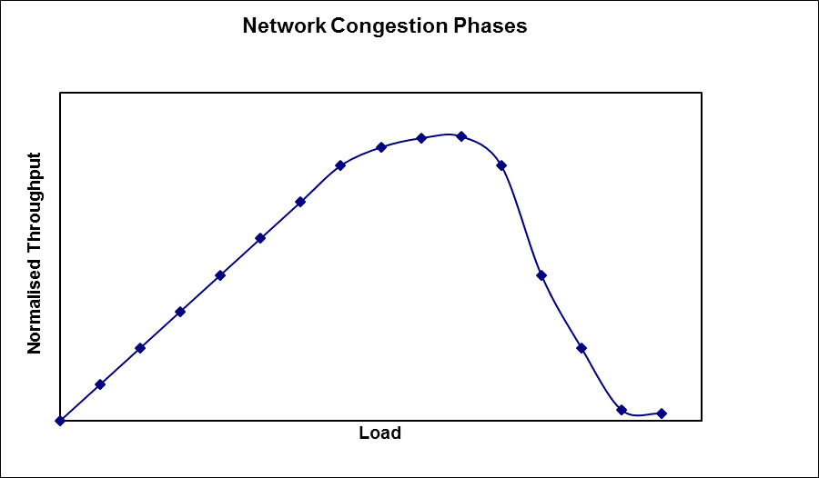
No Congestion
Moderate Congestion
Severe Congestion (Collapse)
no congestion --> near ideal performance
overall moderate congestion:
severe congestion in some nodes
dynamics of the network/routing and overhead of protocol adaptation decreases the network throughput
severe congestion:
loss of packets and increased discards
extended delays leading to timeouts
both factors trigger re-transmissions
leads to chain-reaction bringing the throughput down
For TCP: in slow start, the load starts from cwnd=1 (at the beginning of phase I), then ramps up quickly (exponential growth of cwnd) until a loss is experienced (in phase II or beginning of phase III).
After the loss, if a timeout occurs, TCP goes down to cwnd=1 (at the beginning of phase I) then ramps up to roughly half the load the led to the loss (i.e., half way in phase I).
In congestion avoidance cwnd increases linearly, which means the load increases slowly towards the end of phase I and into phase II, until another loss occurs.
In fast retransmit fast recovery (due to duplicate ACKs), the load is cut in half (half way into phase I), then slow (linear) increase towards phase II (as in congestion avoidance).