January 2011 Edition
Computer Science Department, University of Cape Town
| MIT Notes Home | Edition Home |
| MSc-IT Study Material January 2011 Edition Computer Science Department, University of Cape Town | MIT Notes Home | Edition Home | |
Four basic elements are used to construct data-flow diagrams:
processes
data-flows
data stores
external entities
The rest of this section describes each of the four elements of DFDs, in terms of their purpose, how the element is notated and the rules associated with how the element relates to others in a diagram.
A number of different notations exist for depicting these elements, although it is only the shape of the symbols which vary in each case, not the underlying logic. This unit uses the Select SSADM notation in the description and construction of data-flow diagrams.
As data-flow diagrams are not a part of the UML specification, ArgoUML and Umbrello do not support their creation. However, Dia is free software available for both Windows and Ubuntu which does support data-flow diagrams.
Processes are the essential activities, carried out within the system boundary, that use information. A process is represented in the model only where the information which provides the input into the activity is manipulated or transformed in some way, so that the data-flowing out of the process is changed compared to that which flowed in.
The activity may involve capturing information about something that the organisation is interested in, such as a customer or a customer's maintenance call. It may be concerned with recording changes to this information, a change in a customer's address for example. It may require calculations to be carried out, such as the quantity left in stock following the allocation of stock items to a customer's job; or it may involve validating information, such as checking that faulty equipment is covered by a maintenance contract.
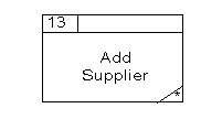
Processes are depicted with a box, divided into three parts.
The top left-hand box contains the process number. This is simply for identification and reference purposes, and does not in any way imply priority and sequence.
The main part of the box is used to describe the process itself, giving the processing performed on the data it receives.
The smaller rectangular box at the bottom of the process is used in the Current Physical Data-Flow Diagram to indicate the location where the processing takes place. This may be the physical location — the Customer Services Department or the Stock Room, for example. However, it is more often used to denote the staff role responsible for performing the process. For example, Customer Services, Purchasing, Sales Support, and so on.
The rules for processes are:
Process names should be an imperative verb specific to the activity in question, followed by a pithy and meaningful description of the object of the activity. Create Contract, or Schedule Jobs, as opposed to using very general or non-specific verbs, such as Update Customer Details or Process Customer Call.
Processes may not act as data sources or sinks. Data flowing into a process must have some corresponding output, which is directly related to it. Similarly, data-flowing out of a process must have some corresponding input to which it is directly related.
Normally only processes that transform system data are shown on data-flow diagrams. Only where an enquiry is central to the system is it included.
Where a process is changing data from a data store, only the changed information flow to the data store (and not the initial retrieval from the data store) is shown on the diagram.
Where a process is passing information from a data store to an external entity or another process, only the flow from the data store to the process is shown on the diagram.
A data-flow represents a package of information flowing between two objects in the data-flow diagram. Data-flows are used to model the flow of information into the system, out of the system, and between elements within the system.
Occasionally, a data-flow is used to illustrate information flows between two external entities, which is, strictly speaking, outside of the system boundaries. However, knowledge of the transfer of information between external entities can sometimes aid understanding of the system under investigation, in which case it should be depicted on the diagram.
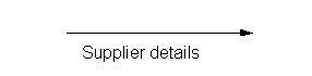
A data-flow is depicted on the diagram as a directed line drawn between the source and recipient of the data-flow, with the arrow depicting the direction of flow.
The directed line is labelled with the data-flow name, which briefly describes the information contained in the flow. This could be a Maintenance Contract, Service Call Details, Purchase Order, and so on.
Data-flows between external entities are depicted by dashed, rather than unbroken, lines.
The rules for drawing data-flows are:
Information always flows to or from a process; the other end of the flow may be an external entity, a data store or another process. An occasional exception to this rule is a data-flow between two external entities.
Data stores may not be directly linked by data-flows; information is transformed from one stored state to another via a process.
Information may not flow directly from a data store to an external entity, nor may it flow from an external entity directly to a data store. This communication and receipt of information stored in the system always takes place via a process.
The sources (where data of interest to the system is generated without any corresponding input) and sinks (where data is swallowed up without any corresponding output) of data-flows are always represented by external entities.
When something significant happens to a data-flow, as a result of a process acting on it, the label of the resulting data-flow should reflect its transformed status. For example, “Telephoned Service Call” becomes “Service Call Form” once it has been logged.
A data store is a place where data is stored and retrieved within the system. This may be a file, Customer Contracts file for example, a catalogue or reference list, Options Lists for example, a log book such as the Job Book, and so on.
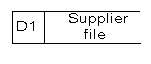
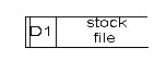
A data store is represented in the data-flow diagram by a long rectangle, containing two locations.
The small left-hand box is used for the identifier, which comprises a numerical reference prefixed by a letter.
The main area of the rectangle is labelled with the name of the data store. Brief names are chosen to reflect the content of the data store.
The rules for representing data stores are:
One convention that could be used is to determine the letter identifying a data store by the store's nature.
“M” is used where a manual data store is being depicted.
“D” is used where it is a computer based data store.
“T” is used where a temporary data store is being represented.
Data stores may not act as data sources or sinks. Data flowing into a data store must have some corresponding output, and vice versa.
Because of their function in the storage and retrieval of data, data stores often provide input data-flows to receive output flows from a number of processes. For the sake of clarity and to avoid crisscrossing of data-flows in the data-flow diagram, a single data store may be included in the diagram at more than one point. Where the depiction of a data store is repeated in this way, this is signified by drawing a second vertical line along the left-hand edge of the rectangle for each occurrence of the data store.
External entities are entities outside of the system boundary which interact with the system, in that they send information into the system or receive information from it. External entities may be external to the whole organisation — as in Customer and Supplier in our running example; or just external to the application area where users' activities are not directly supported by the system under investigation. Accounts and Engineering are shown as external entities as they are recipients of information from the system. Sales also provide input to the system.
External entities are often referred to as sources and sinks. All information represented within the system is sourced initially from an external entity. Data can leave the system only via an external entity.
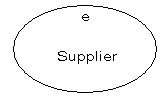
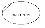
External entities are represented on the diagram as ovals drawn outside of the system boundary, containing the entity name and an identifier.
Names consist of a singular noun describing the role of the entity. Above the label, a lower case letter is used as the identifier for reference purposes.
The rules associated with external entities are:
Each external entity must communicate with the system in some way, thus there is always a data-flow between an external entity and a process within the system.
External entities may provide and receive data from a number of processes. It may be appropriate, for the sake of clarity and to avoid crisscrossing of data flows, to depict the same external entity at a number of points on the diagram. Where this is the case, a line is drawn across the left corner of the ellipse, for each occurrence of the external entity on the diagram. Customer is duplicated in this way in our example.
At times a diagram can be made much clearer by placing more than one copy of an external entity or data store in different places — this can avoid a tangle of crossing data-flows.
Where more than one copy of an external entity appears on a diagram it has a cut off corner in the top left, such as below:
When more than one copy of a data store appears on a diagram it has a cut off left-side, such as below: