January 2011 Edition
Computer Science Department, University of Cape Town
| MIT Notes Home | Edition Home |
| MSc-IT Study Material January 2011 Edition Computer Science Department, University of Cape Town | MIT Notes Home | Edition Home | |
The context diagram is used to establish the context and boundaries of the system to be modelled: which things are inside and outside of the system being modelled, and what is the relationship of the system with these external entities.
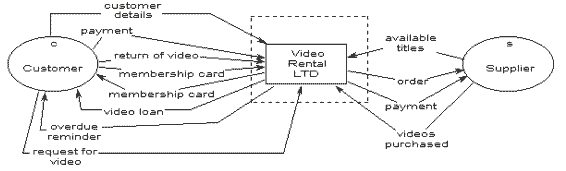
A context diagram, sometimes called a level 0 data-flow diagram, is drawn in order to define and clarify the boundaries of the software system. It identifies the flows of information between the system and external entities. The entire software system is shown as a single process.
A possible context diagram for the Video-Rental LTD case study is shown below.
The process of establishing the analysis framework by drawing and reviewing the context diagram inevitably involves some initial discussions with users regarding problems with the existing system and the specific requirements for the new system. These are formally documented along with any specific system requirements identified in previous studies.
Having agreed on the framework, the detailed investigation of the current system must be planned. This involves identifying how each of the areas included within the scope will be investigated. This could be by interviewing users, providing questionnaires to users or clients, studying existing system documentation and procedures, observation and so on. Key users are identified and their specific roles in the investigation are agreed upon.
In order to produce the context diagram and agree on system scope, the following must be identified:
external entities
data-flows
You may find the following steps useful:
Identify data-flows by listing the major documents and information flows associated with the system, including forms, documents, reference material, and other structured and unstructured information (emails, telephone conversations, information from external systems, etc.).
Identify external entities by identifying sources and recipients of the data-flows, which lie outside of the system under investigation. The actors an any use case models you have created may often be external entities.
Draw and label a process box representing the entire system.
Draw and label the external entities around the outside of the process box.
Add the data-flows between the external entities and the system box. Where documents and other packets of information flow entirely within the system, these should be ignored from the point of view of the context diagram – at this stage they are hidden within the process box.
This system boundary and details depicted in the context diagram should then be discussed (and updated if necessary) in consultation with your customers until an agreement is reached.
Having defined the system boundary and scope, the areas for investigation will be determined, and appropriate techniques for investigating each area will need to be decided.