January 2011 Edition
Computer Science Department, University of Cape Town
| MIT Notes Home | Edition Home |
| MSc-IT Study Material January 2011 Edition Computer Science Department, University of Cape Town | MIT Notes Home | Edition Home | |
As described previously, context diagrams (level 0 DFDs) are diagrams where the whole system is represented as a single process. A level 1 DFD notates each of the main sub-processes that together form the complete system. We can think of a level 1 DFD as an “exploded view” of the context diagram.
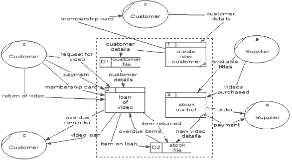
A possible level 1 DFD for the Video-Rental LTD case study is as follows:
Notice that the external entities have been included on this diagram, but outside of the rectangle that represents the boundary of this diagram (i.e., the system boundary). It is not necessary to always show the external entities on level 1 (or lower) DFDs, however you may wish to do so to aid clarity and understanding.
We can see that on this level 1 DFD there are a number of data stores, and data-flows between processes and the data stores.
It is important to notice that the same data-flows to and from the external entities appear on this level 1 diagram and the level 0 context diagram. Each time a process is expanded to a lower level, the lower level diagram must show all the same data-flows into, and out of the higher level process it expands.
If no context diagram exists, first create one before attempting to construct the level 1 DFD (or construct the context diagram and level 1 DFD simultaneously).
The following steps are suggested to aid the construction of Level 1 DFD:
Identify processes. Each data-flow into the system must be received by a process. For each data-flow into the system examine the documentation about the system and talk to the users to establish a plausible process of the system that receives the data-flow. Each process must have at least one output data-flow. Each output data-flow of the system must have been sent by a process; identify the processes that sends each system output.
Draw the data-flows between the external entities and processes.
Identify data stores by establishing where documents / data needs to be held within the system. Add the data stores to the diagram, labelling them with their local name or description.
Add data-flows flowing between processes and data stores within the system. Each data store must have at least one input data-flow and one output data-flow (otherwise data may be stored, and never used, or a store of data must have come from nowhere). Ensure every data store has input and output data-flows to system processes. Most processes are normally associated with at least one data store.
Check diagram. Each process should have an input and an output. Each data store should have an input and an output. Check the system details so see if any process appears to be happening for no reason (i.e., some “trigger” data-flow is missing, that would make the process happen).