January 2011 Edition
Computer Science Department, University of Cape Town
| MIT Notes Home | Edition Home |
| MSc-IT Study Material January 2011 Edition Computer Science Department, University of Cape Town | MIT Notes Home | Edition Home | |
Describe the two main ways in which data-flow diagrams are used to manage the complexity of systems.
A discussion of this question can be found at the end of this chapter.
What are the four different system models which may include data-flow diagrams?
A discussion of this question can be found at the end of this chapter.
What are the external entities in the following diagram Video-Rental LTD case study.
A discussion of this question can be found at the end of this chapter.
What are the data-flows between Supplier and Video-Rental LTD case study in the above diagram?
A discussion of this question can be found at the end of this chapter.
What are the processes in the above diagram Video-Rental LTD case study?
A discussion of this question can be found at the end of this chapter.
What are the data stores in the context diagram Video-Rental LTD case study?
A discussion of this question can be found at the end of this chapter.
What does the zero mean in the top left of the Video-Rental LTD process in the context diagram?
A discussion of this question can be found at the end of this chapter.
Describe the first, top level DFD created for a system.
A discussion of this question can be found at the end of this chapter.
Outline the main roles of Context Diagrams.
A discussion of this question can be found at the end of this chapter.
Follow the suggested steps to create a context diagram for the Video Rental LTD case study.
A discussion of this question can be found at the end of this chapter.
The following Estate Agency case study will be used in this, and some later, review questions. This is the same case study as used in Chapter 4, An Introduction to Analysis and Design, but we will repeat the text here for your convenience.
Clients wishing to put their property on the market visit the estate agent, who will take details of their house, flat or bungalow and enter them on a card which is filed according to the area, price range and type of property.
Potential buyers complete a similar type of card which is filed by buyer name in an A4 binder.
Weekly, the estate agent matches the potential buyer's requirements with the available properties and sends them the details of selected properties.
When a sale is completed, the buyer confirms that the contracts have been exchanged, client details are removed from the property file, and an invoice is sent to the client. The client receives the top copy of a three part set, with the other two copies being filed.
On receipt of the payment the invoice copies are stamped and archived. Invoices are checked on a monthly basis and for those accounts not settled within two months a reminder (the third copy of the invoice) is sent to the client.
Create a context diagram for this Estate Agency case study.
A discussion of this question can be found at the end of this chapter.
What are the processes in the level 1 DFD for the Video Rental case study below?
 |
A discussion of this question can be found at the end of this chapter.
What are the data stores in the level 1 DFD above?
A discussion of this question can be found at the end of this chapter.
What is meant by functional decomposition?
Under what conditions would you decompose a process on a Data-Flow Diagram?
A discussion of this question can be found at the end of this chapter.
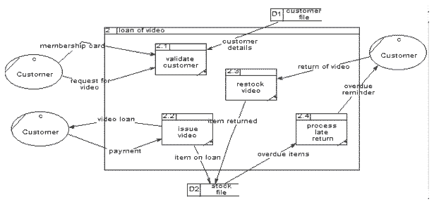
Decompose the Video Rental Level 1 DFD process “loan of video” into a Level 2 DFD.
A discussion of this question can be found at the end of this chapter.
Create a Level 1 DFD for the Estate Agency case study based on the context diagram from the previous Review Question and the case study text.
A discussion of this question can be found at the end of this chapter.
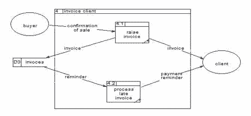
Create a Level 2 DFD for the “invoice client” process of the Estate Agency case study based on the Level 1 DFD from the previous Review Question and the case study text.
A discussion of this question can be found at the end of this chapter.
What are some of the specific benefits of Data Flow Models?
A discussion of this question can be found at the end of this chapter.
Describe each of the main elements of Data-Flow Diagrams.
A discussion of this question can be found at the end of this chapter.
Describe two of the points at which Data-Flow Diagrams are used during systems analysis
A discussion of this question can be found at the end of this chapter.
The details of any level 2 or lower DFD could be displayed in a level 1 DFD, so really there is no reason not to model the entire system in a single level 1 DFD and avoid all the problems of balancing and hierarchical process numbering and so on.
A discussion of this question can be found at the end of this chapter.
There is no facility in the Data-Flow Modelling technique to model the order in which processes occur and data flows. When creating an information system such time-based aspects of a system are just as important as the processes and data themselves.
Why do you think that such a feature not been created as part of Data-Flow Diagrams, and how can system designers get around this omission?
A discussion of this question can be found at the end of this chapter.
Decomposition – which divides complex information into manageable chunks using a hierarchical tree structure. An overview of the problem is presented at the top level of the structure, while lower levels provide increasing depth of detail for narrower areas of the problem
Abstraction – enables software engineers to concentrate on only one aspect of the system at a time. Different models are used to model different perspective of the system. Data-Flow Diagrams concentrate on information flows and the activities which process this information.
Current System Physical model – the physical processes and data-flows and data stores of the current system may be modelled with DFDs (e.g. forms, pieces of paper, physical files and filing systems etc.)
Current System Logical model – the logical processes and data-flows and data stores of the current system may be modelled with DFDs (e.g. logical actions, logical collections of data, logical packages of information flowing etc.)
Required System Logical model – the logical processes and data-flows and data stores of the required system may be modelled with DFDs as part of the specification of the required system
Required System Physical model – the physical processes and data-flows and data stores of the required system may be modelled with DFDs as part of the design for the required system
There are two external entities shown in the above diagram (as ovals):
Customer – a customer who can borrow videos
Supplier – the local supplier
There are 3 data-flows shown in the above diagram (as named arrows):
Available titles – from Supplier to Video-Rental LTD
Order – from Video-Rental LTD to Supplier
Videos – from Supplier to Video-Rental LTD
Supplier – the local supplier
There is just one process in the above diagram (a rectangle with three parts) - Video-Rental LTD
There are no data stores in the above diagram (rectangles with two parts)
The top left part of a process rectangle is the process number. For context diagrams, if any number at all is used, it is usually zero. The zero indicates that this is the whole system, whereas in lower level DFDs numbers like 1 and 3 indicate sub-processes of the whole system. This will become more clear when you have progressed to understanding and creating hierarchical, levelled diagrams.
A Context diagram is the first DFD to be created for a system. It represents a model of the system as a whole (i.e. as a single process) and this systems interactions with external entities that are outside the boundaries of the system, but which provide inputs to, and receive the outputs of the system being modeled.
Context diagrams have the following features:
only one process, representing the whole system
they show no data stores
they show all external entities with which the system exchanges data-flows.
Functional decomposition is the breaking down of higher level processes into their component sub-processes, data-flows and data stores as lower level DFDs.
The condition to decide to decompose a process is any time where there is some detailed aspect of the system that is not modeled by the process description alone — i.e. when a lower level DFD provides something more to the software engineer, such as sub processes, additional data stores, and data-flows that are used only for the process and which have not been modeled at the higher level DFD.
Identify data-flows by listing the major documents and information flows associated with the system.
You may find the use of the following kind of table is useful:
| data-flow | Sender | Receiver |
|---|---|---|
From the case study we can underline all potential data flows INTO AND OUT OF THE SYSTEM. At this point look for any possible data-flows, we can change our minds at any time in the process of creating a context diagram. We are not worried about data-flows that seem to be within the system at present, so the sender and receiver should always be either an external entity, or the system itself.
Video-Rental LTD is a small video rental store. The store lends videos to customers for a fee, and purchases its videos from a local supplier.
A customer wishing to borrow a video provides the empty box of the video they desire, their membership card, and payment – payment is always with the credit card used to open the customer account. The customer then returns the video to the store after watching it.
If a loaned video is overdue by a day the customer's credit card is charged, and a reminder letter is sent to them. Each day after that a further chard is made, and each week a reminder letter is sent. This continues until either the customer returns the video, or the charges are equal to the cost of replacing the video.
New customers fill out a form with their personal details and credit card details, and the counter staff give the new customer a membership card. Each new customer's form is added to the customer file.
The local video supplier sends a list of available titles to Video-Rental LTD, who decide whether to send them an order and payment. If an order is sent then the supplier sends the requested videos to the store. For each new video a new stock form is completed and placed in the stock file.
| data-flow | Sender | Receiver |
|---|---|---|
| video | system | customer |
| customer detail | customer | system |
| membership card | customer | system |
| membership card | system | customer |
| empty video box | customer | system |
| payment | customer | system |
| return of video | customer | system |
| credit card charge | system | customer (or credit card firm) |
| overdue reminder letter | system | customer |
| available titles | supplier | system |
| order | system | supplier |
| payment | system | supplier |
| requested videos | supplier | system |
| stock form | system | system |
Let us consider each data-flow in turn:
video by customer when joining the store — this is a strong candidate data-flow, though we might name it 'video loan' or 'details of loaned video'
customer details by customer when joining the store — this is a strong candidate data-flow
membership card issued to customer — this is a strong candidate data flow
membership card presented by customer when renting a video — this is a strong candidate data-flow
empty video box presented by customer when renting a video — this is a strong candidate data-flow, but perhaps should be call 'request for video' or something similar
payment by customer when renting a video — this is a strong candidate data flow
return of video by customer — this is a strong candidate data flow, although the data might be 'returned video' or 'returned video details'
credit card charge by system — this is a strong candidate data flow, but in fact we have already identified a payment by the customer (when renting a video) and we could just consider this to be anther example of customer payment (for simplicity, although alternatively we could consider this a separate data-flow, the decision could be influenced on the sophistication of the systems processing of payments, and might be delayed until more detailed DFDs are produced later in the analysis procedure)
overdue reminder letter from system — this is a strong candidate data flow
payment by system for order — this is a strong candidate data flow
list of available titles from supplier — this is a strong candidate data flow
the requested videos from supplier — this is a strong candidate data flow, although might be called something like 'videos purchased'
stock form — this last data-flow is within the system, so this will not be used in the context diagram but will probably appear in a more detailed DFD later
You might have noticed
Identify external entities by identifying sources and recipients of the data-flows, which lie outside of the system under investigation.
This step is easy if we have created a table like the above, since we can just create a list of all the different entities:
customer
supplier (a candidate might be the credit card company, but we shall choose to consider the customer to be charged in this case for simplicity)
Draw and label a process box representing the entire system.
 |
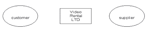
Draw and label the external entities around the outside of the process box.
We just need to add external entity symbols for 'customer' and 'supplier'.
 |
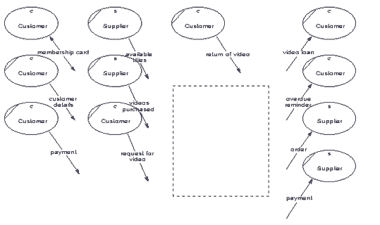
Add the data-flows between the external entities and the system box
we now need to add those data-flows earlier:
| data-flow | Sender | Receiver |
|---|---|---|
| video loan | system | customer |
| customer details | customer | system |
| membership card | customer | system |
| membership card | system | customer |
| request for video | customer | system |
| payment | customer | system |
| return of video | customer | system |
| overdue reminder | system | customer |
| available titles | supplier | system |
| order | system | supplier |
| payment | system | supplier |
| requested video | supplier | system |
We can do a quick check when we have created the diagram by counting the number of flows out of, and into each entity.
From column 'sender' we can see there should be:
5 data-flows out of the system
5 data-flows out of customer
2 data-flows out of supplier
From column 'receiver' we can see there should be:
7 data-flows into the system.
3 data-flows into customer
2 data-flows out of supplier
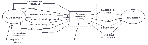
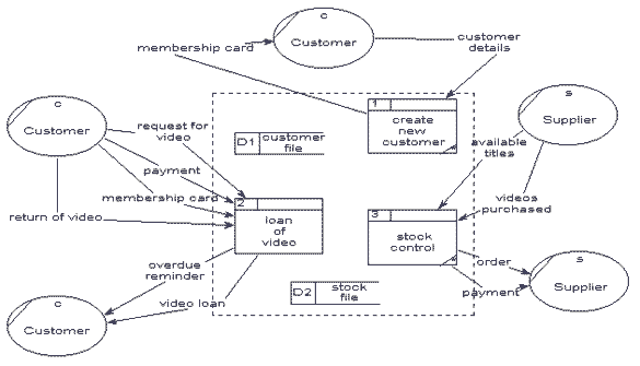
Our context diagram looks as follows:
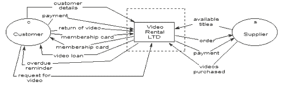 |
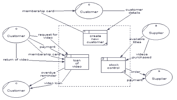
There are 3 data-flows shown in the above diagram (as named arrows):
Create new customer
Loan of video
Stock control
First we start with the context diagram, since all external entities and data-flows on this diagram must appear on our Level 1 DFD:
 |
We can now create an 'empty' Level 1 DFD with these entities and data-flows:
 |
Identify processes. Each data-flow into the system must be received by a process. Each process must have at least one output data-flow. Each output data-flow of the system must have been sent by a process.
Now we need to identify the recipient and sending processes of the system for each data-flow. We need to replace with a system process each occurrence of 'system' as the sender or recipient in the table of data-flows created previously.
Possible processes have been inserted in the following table:
| Data-Flow | Sender | Customer |
|---|---|---|
| video loan | system - loan of video | customer |
| customer details | customer | system - create new customer |
| membership card | customer | system - loan of video |
| membership card | system - create new customer | customer |
| request for video | customer | system - loan of video |
| payment | customer | system - loan of video |
| return of video | customer | system - loan of video |
| overdue reminder | system - loan of video | customer |
| available titles | supplier | system - stock control |
| order | system - stock control | supplier |
| payment | system - stock control | supplier |
| requested videos | supplier | system - stock control |
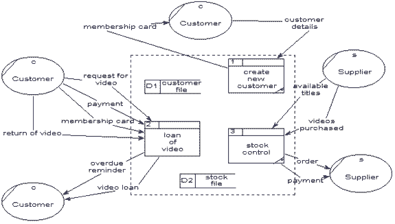
Draw the data-flows between the external entities and processes. After creating process boxes and drawing the data-flows the diagram looks as follows:
 |
Identify data stores by establishing where documents / data needs to be held within the system. Add the data stores to the diagram, labelling them with their local name or description.
There seem to be 2 main data stores required: a store of customer details 'customer file' and a store of which videos are in stock 'stock file'.
After adding these to the diagram looks as follows:
 |
Add data-flows flowing between processes and data stores within the system. Each data store must have at least one input data-flow and one output data-flow.
We can create a table to indicate which processes send and receive data from each data store:
| Data store | data-flow IN FROM | data-flow OUT TO |
|---|---|---|
| customer file | customer details FROM create new customer | customer details TO loan of video |
| stock file | new video details FROM stock control | overdue items TO loan of video |
After adding these data-flows the diagram looks as follows:
 |
check diagram No record seems to be made of when a video is lent to a customer — there ought to be a data-flow from 'loan of video' to 'stock file' called something like 'item on loan'. Likewise when an item is returned the details should be recorded in a data-flow called something like 'item returned'.
Apart from these extra two data-flows the diagram appears to be correct.
So our Level 1 DFD for the Video Rental case study is now:
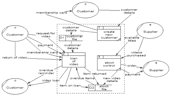 |
Make the process box on the Level 1 diagram the system boundary on the Level 2 diagram that decomposes it.
This gives us the following, “empty” Level 2 DFD:
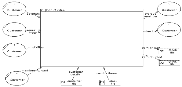 |
Identify the processes inside the Level 2 system boundary and draw these processes and their data-flows.
For each data-flow into and out of the process for which this Level 2 diagram is being created we need to identify an appropriate sub-process to receive and send the data flows. The following table lists each data-flow and suggests a suitable sub-process to receive/send the data-flow:
| data-flow | Sender | Receiver |
|---|---|---|
| video loan | loan of video - process loan | customer |
| membership card | customer | loan of video - validate customer |
| request for video | customer | loan of video - validate customer |
| payment | customer | loan of video - issue video |
| return of video | customer | loan of video - restock video |
| customer details | customer-file | loan of video - validate customer |
| overdue items | stock-file | loan of video - process late return |
| item returned | loan of video - restock video | stock-file |
| item on loan | loan of video - issue video | stock-file |
| overdue reminder | loan of video - process late return | customer |
Adding these processes and data-flows to the diagram we get the following:
 |
Identify any data stores that exist entirely within the Level 2 boundary, and draw these data stores: For this example there don't appear to be any “local” data stores
Identify data-flows between the processes and data stores that are entirely within the Level 2 system boundary: Since there are no local data stores, there are no data-flows between processes and data stores to be added.
Check the diagram: Upon checking the diagram, we find that the process “validate customer” has no output data flows. Looking more closely we see that a plausible data flow out of “validate customer” would be something like “loan permission”.
Upon adding this new data-flow the diagram looks as follows:
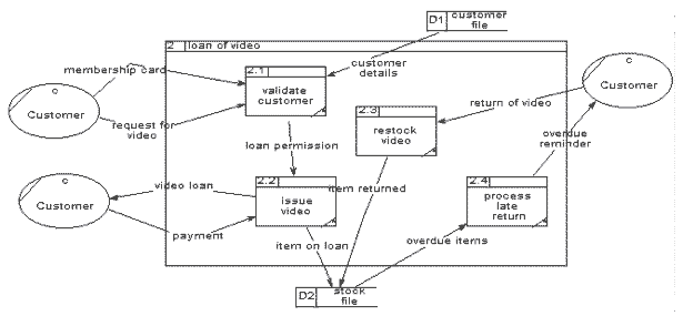 |
Identify data-flows by listing the major documents and information flows associated with the system.
You may find the use of the following kind of table is useful:
| data-flow | Sender | Receiver |
|---|---|---|
From the case study we can underline all potential data flows INTO and OUT OF THE SYSTEM. At this point look for any possible data-flows, we can change our minds at any time in the process of creating a context diagram. We are not worried about data-flows that seem to be within the system at present, so the sender and receiver should always be either an external entity, or the system itself.
Clients wishing to put their property on the market visit the estate agent, who will take details of their house, flat or bungalow and enter them on a card which is filed according to the area, price range and type of property .
Potential buyers complete a similar type of card which is filed by buyer name in an A4 binder.
Weekly, the estate agent matches the potential buyer' requirements with the available properties and sends them the details of selected properties.
When a sale is completed, the buyer confirms that the contracts have been exchanged, client details are removed from the property file, and an invoice is sent to the client. The client receives the top copy of a three part set, with the other two copies being filed.
On receipt of the payment the invoice copies are stamped and archived. Invoices are checked on a monthly basis and for those accounts not settled within two months a reminder (the third copy of the invoice) is sent to the client.
We can build a table of these data-flows, and the senders and receivers of these flows.
| data-flow | Sender | Receiver |
|---|---|---|
| house details | client | system |
| buyer details | buyer | system |
| selected properties | system | buyer |
| contract | buyer | client |
| invoice | system | client |
| payment | client | system |
| reminder | system | client |
Rejected candidates for data-flows include:
the internal copies of the invoice - these data-flows do not go outside the system boundary so will not be part of this context diagram (but may feature on a more detailed DFD later)
the client details card is filed IN the system, so this internal data-flow will not feature on the context diagram
It is worth noting that the exchange of contracts between client and buyer is not a data-flow into or out of the system, but this data-flow between external entities is relevant so ought to be notated on the context diagram.
Identify external entities by identifying sources and recipients of the data-flows, which lie outside of the system under investigation.
This step is easy if we have created a table like the above, since we can just create a list of all the different entities: client, buyer.
Draw and label a process box representing the entire system:
 |
Draw and label the external entities around the outside of the process box. We just need to add external entity symbols for 'client' and 'buyer'
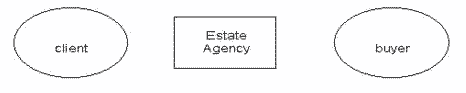 |
Add the data-flows between the external entities and the system box. We now need to add those data-flows earlier. Our context diagram looks as follows:
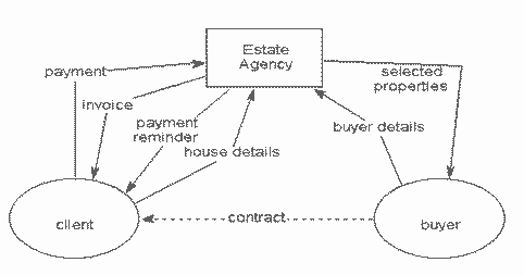 |
We can check the diagram quickly looking at the table:
| data-flow | Sender | Receiver |
|---|---|---|
| house details | client | system |
| buyer details | buyer | system |
| selected properties | system | buyer |
| contract | buyer | client |
| invoice | system | client |
| payment | client | system |
| reminder | system | client |
Client should send 2 data-flows, and receive 3.
Buyer should send 2 data-flows and receive 1.
System should send 3 data-flows and receive 3.
We should start with the context diagram, and create an 'empty' Level 1 DFD with all the same external entities and data-flows:
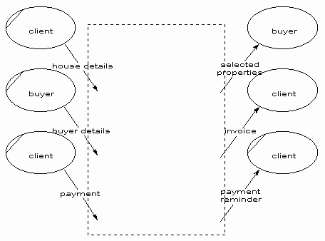 |
Identify processes - Each data-flow into and out of the system must be received by /send by a process. Now you need to identify the recipient and sending processes of the system for each data-flow. We need to replace with a system process each occurrence of 'system' as the sender or recipient in the table of data-flows created previously. Possible processes have been inserted in the following table:
| data-flow | Sender | Receiver |
|---|---|---|
| house detail | client | system - record new client |
| buyer details | buyer | system - record new buyer |
| selected properties | system - match properties | buyer |
| contract | buyer | client |
| invoice | system - invoice client | client |
| payment | client | system - archive sale |
| reminder | system - invoice client | client |
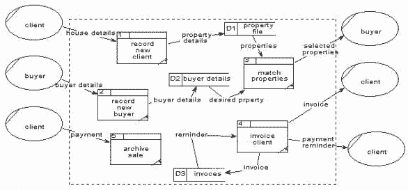
Draw the data-flows between the external entities and processes. We can now add these processes to the diagram, and connect the appropriate data-flows:
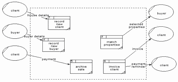 |
Identify data stores by establishing where documents / data needs to be held within the system. Add the data stores to the diagram, labelling them with their local name or description. There are two 'card' stores (clients and buyers) so these should be data stores 'property file' and 'buyer details'. A file need to be kept for the invoice copies 'invoices'. We can add these data stores to the diagram:
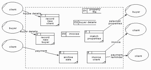 |
Add data-flows flowing between processes and data stores within the system. Each data store must have at least one input data-flow and one output data-flow (otherwise data may be stored, and never used, or a store of data must have come from nowhere!). Ensure every data store has input and output data-flows to system processes. Most processes are normally associated with at least one data store.
We can create a table to indicate which processes send and receive data from each data store:
| Data store | data-flow IN FROM | data-flow OUT TO |
|---|---|---|
| property file | property details FROM record new client | properties TO match properties |
| buyer details | buyer details FROM record new buyer | desired property TO match properties |
| invoices | invoice FROM invoice client | reminder TO invoice client |
These data-flows can be added to the diagram:
 |
Check diagram. We now can check the diagram for correctness, and find a process that has no output data-flow 'archive sale'. An appropriate data-flow, into data store 'invoices' would be something like 'record of payment'. The consistent and balanced Level 1 DFD now looks as follows:
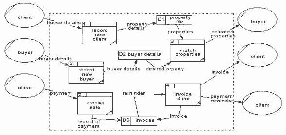 |
However, there is another problem with the diagram — what causes the process 'invoice client' to send an invoice or reminder to the client? The only input to the process 'invoice client' is a 'reminder' from the 'invoices' data store. The answer is that there are two things that trigger this process to send a data-flow to the client:
knowledge that sale has been completed
knowledge that a payment on an issued invoice is overdue
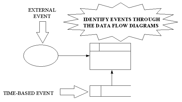
The second is a time-based event, and not modelled explicitly in Data-Flow Diagrams. However, the first indicates there should be a data-flow from an external entity to the system indicating that contracts have been exchanged. If we look carefully at the case study again, we find that:
When a sale is completed, the buyer confirms that the contracts have been exchanged, client details are removed from the property file, and an invoice is sent to the client.
This must mean that the buyer informs the system that the sale is complete, so we must create a new data-flow from 'buyer' to 'invoice client' called something like 'confirmation of sale'. (NOTE: Since we are adding a new data-flow between the system and the external entities, we shall have to update the parent diagram — if we forget we will be reminded by any CASE tool consistency checker).
We also notice there should be a data-flow of 'client to delete' from process 'invoice client' to the data store 'property file'.
Our Level 1 DFD now looks as follows:
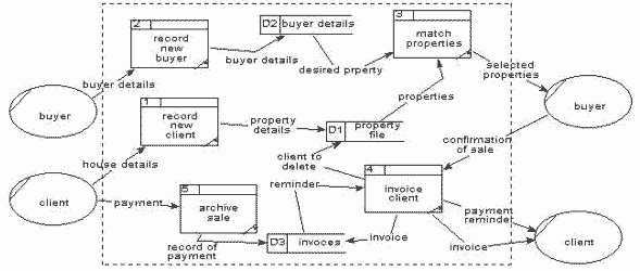 |
Make the process box on the Level 1 diagram the system boundary on the Level 2 diagram that decomposes it.
We should start with the Level 1 DFD, and create an 'empty' Level 2 DFD with all the same external entities and data-flows as the “invoice client” process.
This gives us the following, “empty” Level 2 DFD:
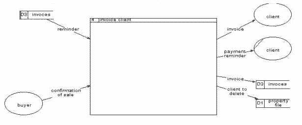 |
Identify the processes inside the Level 2 system boundary and draw these processes and their data-flows.
For each data-flow into and out of the process for which this Level 2 diagram is being created we need to identify an appropriate sub-process to receive and send the data-flows. The following table lists each data-flow and suggests a suitable sub-process to receive/send the data-flow:
| data-flow | sender | receiver |
|---|---|---|
| invoice | invoice client - raise invoice | client |
| payment reminder | invoice client - process late payment | client |
| reminder | invoice client - process late payment | invoice client - process late payment |
| invoice | invoice client - raise invoice | invoices |
| confirmation of sale | buyer | invoice client - raise invoice |
| client to delete | invoice client - ???? | property file |
The last row in the table above is interesting — there doesn't appear to be a sub-process inside the “invoice client” process that creates the data-flow “client to delete”. Looking carefully at the Level 1 DFD we can see that the “archive sale” process is probably most appropriate to be sending the property file the details of which client to delete, since it is this process that receives the payment from the client. Therefore we need to delete this “client to delete” data-flow from the Level 2 DFD, and change the Level 1 DFD to have this data-flow from “achieve sale” to the “property file”.
Adding these processes and data-flows to the diagram we get the following:
 |
Identify any data stores that exist entirely within the Level 2 boundary, and draw these data stores. For this example there don't appear to be any “local” data stores
Identify data-flows between the processes and data stores that are entirely within the Level 2 system boundary. Since there are no local data stores, there are no data-flows between processes and data stores to be added.
Check the diagram. There appear to be no inconsistencies with the diagram, so our final diagram stays the same.
Data-Flow Diagrams concentrate on the flow and transformation of data. High level Data-Flow Diagrams are decomposed to a set of more detailed diagrams.
Processes – the activities carried out by the system.
the data inputs and outputs to/from these activities.
where information is stored within the system.
the sources of data-flows into the system, and recipients of information leaving the system.
Any two of the following would be fine:
Current System Physical model – the physical processes and data-flows and data stores of the current system may be modeled with DFDs (e.g. forms, pieces of paper, physical files and filing systems etc.) [investigating current system]
Current System Logical model – the logical processes and data-flows and data stores of the current system may be modeled with DFDs (e.g. logical actions, logical collections of data, logical packages of information flowing etc.) [investigating current system]
Required System Logical model – the logical processes and data-flows and data stores of the required system may be modeled with DFDs as part of the specification of the required system
Required System Physical model – the physical processes and data-flows and data stores of the required system may be modeled with DFDs as part of the design for the required system
While, theoretically, it would be valid to model an entire system in a single level 1 DFD, for any non-trivial system such a diagram would fill an entire wall or floor of a very large room !
In the same way the a physical organisation is divided into departments or sections (or faculties for a University), to gain the benefits of local organisation and ability to manage, so levelled DFDs allow different logical functions of organisations to be abstracted and modelled together. So all sales functions of an organisation can be modelled as a single “sales” process, and then described at a lower level in more detail.
Obviously a major advantage of levelling is that the complexity of any single diagram can be restricted so as not to overwhelm the reader.
It should be remembered that each modelling technique (such as Data-Flow Diagrams and Entity-Relationship Diagrams) only presents one aspect of the system — the model of the complete system is formed when a number of different models are put together.
The three main traditional modelling techniques for systems analysis and specification are:
Data-Flow diagrams
Entity Relationship diagrams
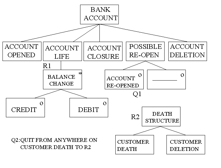
Entity Life histories
The third of these, Entity Life Histories (ELHs), is the modelling technique that represents those aspects of a system that change over time. Entity Life Histories are introduced in a later unit, and play an important role in relating the processes and data stores of DFDs with the logical data models of Entity Relationship Diagrams.
Any particular modelling technique will have been designed to represent only certain aspects of a system, since any non-trivial system would be much to complex to ever model with a single technique — any resulting diagram or set of diagrams would contain more information that would be usefully understandable by users and system developers.